Lab 3 walked through the 802.1D election. Same algorithm runs in production today — but nobody runs the original timing. After a link failure, classic STP holds the network in listening / learning states for 30 to 50 seconds before traffic flows again. That was acceptable in 1998. It is not acceptable now.
Rapid Spanning Tree (802.1w, 2001) keeps the entire election logic and replaces the timers with a proposal / agreement handshake between switches. Edge ports skip the delay states entirely. The result: a topology change reconverges in well under a second on point-to-point links — fast enough that a continuous ping doesn't drop a single packet on a healthy LAN.
This lab builds a 3-switch triangle in Packet Tracer, enables Rapid-PVST+, and uses Simulation Mode + a continuous ping to watch RSTP reconverge in real time when you shut down the active path.
★ WHAT'S DIFFERENT FROM 802.1D
Designated Port — same as STP, best port on a segment
Alternate Port — pre-computed backup for the Root Port (replaces "Blocking" in this case)
Backup Port — pre-computed backup for a Designated Port on a shared segment (rare — only on hubs)
Discarding — collapses 802.1D's Disabled, Blocking, and Listening
Learning — building MAC table, no forwarding
Forwarding — fully operational
On shared segments (half-duplex / hubs), RSTP falls back to legacy timers. Modern LANs are full duplex everywhere, so this rarely matters.
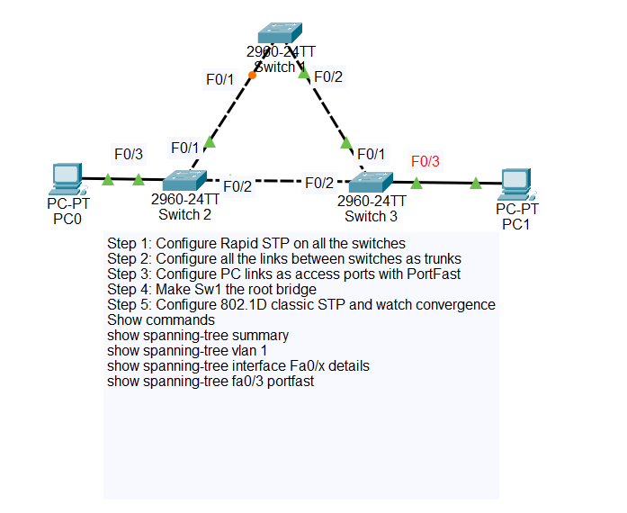
★ TOPOLOGY
SW2 — Cisco 2960-24TT
SW3 — Cisco 2960-24TT
PC0 — connected to SW2
PC1 — connected to SW3
SW1 Fa0/2 ↔ SW3 Fa0/1 (trunk)
SW2 Fa0/2 ↔ SW3 Fa0/2 (trunk — this becomes the redundant path)
SW2 Fa0/3 → PC0 (access — edge port)
SW3 Fa0/3 → PC1 (access — edge port)
★ IP ADDRESSING
One subnet, default VLAN 1. Keep it simple — this lab is about the spanning tree, not IP design.
| DEVICE | IP ADDRESS | SUBNET | CONNECTED TO |
|---|---|---|---|
| PC0 | 192.168.1.10 | /24 | SW2 Fa0/3 |
| PC1 | 192.168.1.20 | /24 | SW3 Fa0/3 |
★ STEP 1 — CABLE THE TOPOLOGY
In Packet Tracer, drop in 3x 2960-24TT switches, 2x PCs. Use straight-through copper for PC-to-switch and switch-to-switch (Packet Tracer auto-negotiates the right cable type with auto-MDIX). Wait for the link lights to come up green on the switch ports — that takes the 30-second 802.1D listening / learning before STP allows forwarding, which by itself is a good demo of why we're upgrading to RSTP.
show spanning-tree summary before you start the convergence demo.
★ STEP 2 — ENABLE RAPID-PVST ON ALL SWITCHES
Run on SW1, SW2, and SW3:
That single command flips every VLAN's STP instance from 802.1D to 802.1w on this switch. The switch immediately starts sending RSTP-format BPDUs and negotiates with neighbours.
★ STEP 3 — FORCE SW1 AS ROOT BRIDGE
Without configuration, the lowest MAC wins — effectively random. Pin SW1 as root so the topology is predictable for the demo.
With SW1 at priority 4096 and the others at the default 32768, SW1 has the lowest Bridge ID and wins the election regardless of MAC.
★ STEP 4 — TRUNK THE SWITCH-TO-SWITCH LINKS
RSTP works on access ports too, but trunks are the realistic case and they make the link-type point-to-point detection unambiguous. Run on the appropriate ports of each switch.
★ STEP 5 — DECLARE EDGE PORTS (PORTFAST)
The PC ports should be edge ports. An edge port is RSTP's name for a port that connects to an end device — it skips Discarding and Learning entirely and goes straight to Forwarding the instant the link comes up. This is what eliminates the classic 30-second wait for a PC to get DHCP.
spanning-tree bpduguard enable as a safety net — if any BPDU is ever seen on a portfast port, the port shuts down.
★ STEP 6 — ASSIGN IPs AND VERIFY ELECTION
Click each PC (PC0 and PC1), open the Desktop tab → IP Configuration, set the static address from the table above. Then verify the spanning tree on each switch.
Read the role column carefully. RSTP labels the redundant blocked port as Altn (Alternate), not BLK. The state column shows DIS for discarding rather than BLK for blocking.
SW2 — Fa0/1 = RP (toward SW1, cost 19), Fa0/2 = either DP or Altn (one of SW2/SW3 wins the SW2↔SW3 segment by lower MAC).
SW3 — Fa0/1 = RP, Fa0/2 = whichever role SW2 didn't take.
Note which switch ended up with the Alternate port — that's the switch you'll use to time the convergence demo.
★ STEP 7 — WATCHING RSTP CONVERGE
This is the part the lab is built around. You're going to start a continuous ping that traverses the active path, then break the active path and time how long it takes the alternate to take over.
SETUP THE PING
On PC0, open Desktop → Command Prompt:
You should see Reply from 192.168.1.20 ... every second. The ping is currently traversing whatever path RSTP elected — most likely PC0 → SW2 → SW1 → SW3 → PC1.
OPEN SIMULATION MODE TO SEE THE BPDUs
Bottom-right corner of Packet Tracer, switch from Realtime to Simulation. In the Event List filters, click Edit Filters → EDIT ACL FILTERS → check STP only (uncheck everything else). Hit Auto Capture / Play.
You'll see RSTP BPDUs flow between switches every 2 seconds (Hello timer). Click any BPDU envelope in the topology to inspect the OSI layer breakdown — the Type field shows 0x02 for RSTP (vs 0x00 for legacy STP). This is also how you confirm visually that you're actually running RSTP and not classic STP.
TRIGGER THE FAILURE
Switch back to Realtime mode so the ping keeps flowing. Identify the switch holding the active path to root — let's say SW2's Fa0/1 is the Root Port. Open SW2's CLI:
The instant you hit Enter, watch the ping window. With Rapid-PVST+, you should see at most one or two timed-out replies before the ping resumes. RSTP detected the link loss, the Alternate port on SW3 (or SW2, depending on the election) immediately transitioned to Root Port and Forwarding state via the proposal / agreement exchange.
BRING IT BACK AND COMPARE TO LEGACY STP
Re-enable the link, then flip the switches back to legacy mode and repeat the demo:
This time count the ping timeouts. You'll see roughly 15 to 30 seconds of dropped packets as the topology runs Max Age + Listening + Learning before the alternate path forwards. That's the exact problem RSTP solves.
802.1D failover: 15–30 dropped pings (15–30 seconds).
Same topology. Same physical recovery path. The only thing that changed was the protocol's willingness to skip the safety timers when it has pre-computed alternates.
★ OTHER WAYS TO TRIGGER CONVERGENCE
Once the lab is built, you can keep poking it. Each of these prompts a different RSTP behavior:
Force a re-election — Lower another switch's priority below SW1's:
spanning-tree vlan 1 priority 0. Whole tree rebuilds.Test PortFast — Power-cycle a PC (right-click → power button). With portfast, the switch port goes straight to forwarding. Without portfast, watch the ~30s wait.
Use the Time slider — In Simulation mode, the timeline at the bottom shows exact frame timing. Step through the proposal / agreement BPDU exchange one packet at a time after a failure.
★ VERIFICATION CHEAT SHEET
★ COMMON GOTCHAS
duplex full.
spanning-tree bpduguard enable per-port, or globally with spanning-tree portfast bpduguard default.
★ LAB DOWNLOAD
Built and tested in Packet Tracer 8.x. Drop the .pkt file, hit play, and run through Steps 5–7 to see RSTP do its thing.
Includes pre-built topology, Step 7 ready to trigger ⬇ DOWNLOAD .PKT