Open the lab
[ YOUR LAB FILE ]
Download the starting topology, then work through the lesson in SwitchLab.
- Save the .swlab file without renaming its extension.
- Open SwitchLab. Import and export controls currently require a desktop-width window. On a smaller screen, Tools → Fit brings the topology into view.
- Select Import Sandbox (folder icon), choose the downloaded file, and confirm the device and cable counts below.
- Select a device, then choose Open device on desktop or its name in the bottom bar on smaller screens. Select CLI for switches/routers or Desktop → Terminal for PCs. Enter
enableonly when the prompt ends in >. - Follow this page beside the simulator. Use a free account to export your work. Reimport the original download to restart; export any work you want to keep first.
Prerequisites
- Complete Static Routing Requirements or understand connected routes and next-hop forwarding.
- Recognize /24 LAN masks, /30 transit masks and IOS configuration modes.
Topology
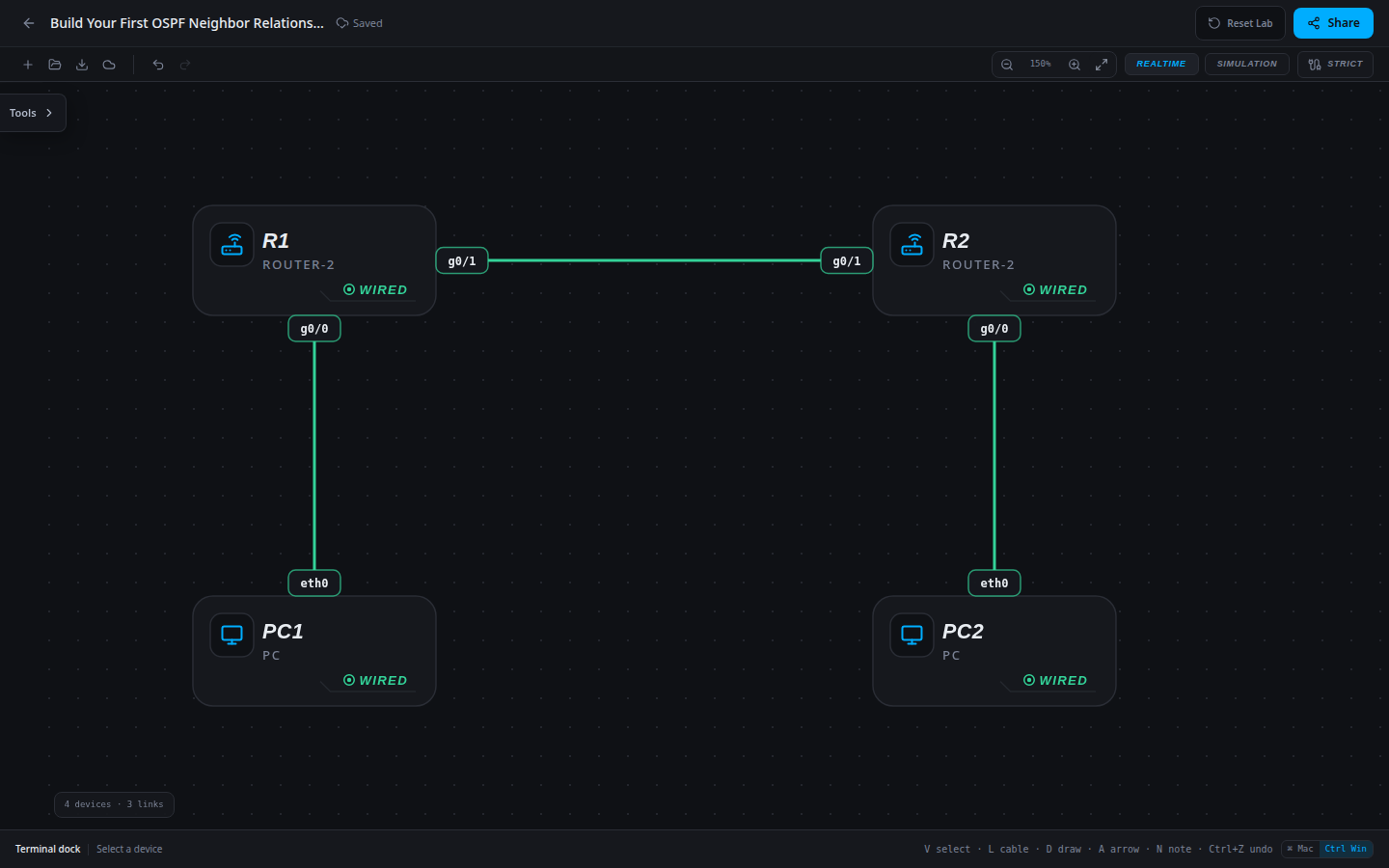
4 devices · 3 links
Scenario
Two small offices have working Ethernet and IPv4 addressing. Their routers know only connected networks. Replace manual route maintenance with one area-0 OSPF process per router and verify both the neighbor relationship and user traffic.
Objectives
- Distinguish connected routes from OSPF-learned routes.
- Configure an OSPF process with a unique router ID and matching area on each router.
- Verify FULL neighbors, remote LAN routes and bidirectional workstation delivery.
CCNA blueprint
200-301 v1.1 objectives — this lab covers the following specific skills, not every subtopic in the domain.
- 3.4.a — Troubleshoot single-area OSPFv2 neighbor adjacency.
- 3.4.d — Identify peers by router ID.
- 3.1.a — Distinguish OSPF-learned routes from connected routes.
Starting information
- No OSPF process or static route is configured. All interfaces are enabled and addressed.
- Use process 1 and area 0. Assign router ID 1.1.1.1 to R1 and 2.2.2.2 to R2 before enabling interfaces in OSPF. Router IDs identify routers; they are not extra interface addresses.
- Enable OSPF on both the transit subnet and each local LAN. Keep g0/0 passive because there is no router peer on either workstation LAN.
| Host | IPv4 address | Mask | Gateway |
|---|---|---|---|
| PC1 | 10.10.10.10 | 255.255.255.0 | 10.10.10.1 |
| PC2 | 10.20.20.20 | 255.255.255.0 | 10.20.20.1 |
| Router | Interface | IPv4 address | Mask |
|---|---|---|---|
| R1 | g0/0 | 10.10.10.1 | 255.255.255.0 |
| R1 | g0/1 | 10.0.12.1 | 255.255.255.252 |
| R2 | g0/0 | 10.20.20.1 | 255.255.255.0 |
| R2 | g0/1 | 10.0.12.2 | 255.255.255.252 |
| Device / port | Device / port |
|---|---|
| PC1 / eth0 | R1 / g0/0 |
| R1 / g0/1 | R2 / g0/1 |
| PC2 / eth0 | R2 / g0/0 |
Tasks
- Test each local gateway and predict why the remote PC ping fails. Inspect the empty OSPF neighbor table and the connected routes.
- On R1 enter
router ospf 1, thenrouter-id 1.1.1.1. Addnetwork 10.0.12.0 0.0.0.3 area 0for the transit andnetwork 10.10.10.0 0.0.0.255 area 0for the LAN. A network statement matches local interface addresses; the wildcard is not a subnet mask. - Set
passive-interface g0/0on R1. This suppresses neighbor exchanges on that LAN while retaining its advertisement. Return to EXEC withend. - Repeat on R2 using router ID 2.2.2.2, the same transit statement, and the R2 LAN 10.20.20.0/24. Keep its LAN passive too.
- Identify the peer ID, peer transit address and FULL state in each neighbor table. Find the O-coded remote /24 route, then test both workstation directions and save.
Useful commands
show ip interface brief
show ip ospf neighbor
show ip ospf interface brief
show ip route
show running-config
copy running-config startup-config
Progressive hints
Hint 1
A cable and an IP address do not enable OSPF. Each router needs a routing process and participating interfaces.
Hint 2
Use wildcard 0.0.0.3 for the /30 transit and 0.0.0.255 for a /24 LAN. The two transit interfaces must share an area.
Hint 3
The transit g0/1 needs an active neighbor exchange. Keep only g0/0 passive and verify remote routes after FULL adjacency appears.
Verification
- Before configuration, each PC reaches its gateway but the remote workstation fails.
- R1 sees peer 2.2.2.2 and R2 sees 1.1.1.1 in FULL state. Peer addresses are 10.0.12.2 and 10.0.12.1 respectively.
- R1 learns O 10.20.20.0/24; R2 learns O 10.10.10.0/24. Both LAN interfaces remain passive.
- PC1 to 10.20.20.20 and PC2 to 10.10.10.10 succeed. This model shows deterministic converged state, not measured Hello timing.
Solution / walkthrough
Show Solution
Use enable only from a > prompt; if already at #, begin with configure terminal.
R1
Set the stable router ID before enabling OSPF interfaces. The transit forms the adjacency; the passive LAN contributes its prefix without seeking a workstation neighbor.
enable
configure terminal
router ospf 1
router-id 1.1.1.1
network 10.10.10.0 0.0.0.255 area 0
network 10.0.12.0 0.0.0.3 area 0
passive-interface g0/0
end
copy running-config startup-config
R2
Set the stable router ID before enabling OSPF interfaces. The transit forms the adjacency; the passive LAN contributes its prefix without seeking a workstation neighbor.
enable
configure terminal
router ospf 1
router-id 2.2.2.2
network 10.20.20.0 0.0.0.255 area 0
network 10.0.12.0 0.0.0.3 area 0
passive-interface g0/0
end
copy running-config startup-config
Run every verification check above after the changes. A saved configuration alone does not prove packet delivery.