Open the lab
[ YOUR LAB FILE ]
Download the starting topology, then work through the lesson in SwitchLab.
- Save the .swlab file without renaming its extension.
- Open SwitchLab. Import and export controls currently require a desktop-width window. On a smaller screen, Tools → Fit brings the topology into view.
- Select Import Sandbox (folder icon), choose the downloaded file, and confirm the device and cable counts below.
- Select a device, then choose Open device on desktop or its name in the bottom bar on smaller screens. Select CLI for switches/routers or Desktop → Terminal for PCs. Enter
enableonly when the prompt ends in >. - Follow this page beside the simulator. Use a free account to export your work. Reimport the original download to restart; export any work you want to keep first.
Prerequisites
- Recognize user EXEC (>), privileged EXEC (#), and configuration prompts.
- Understand an IPv4 address and /24 subnet.
Topology
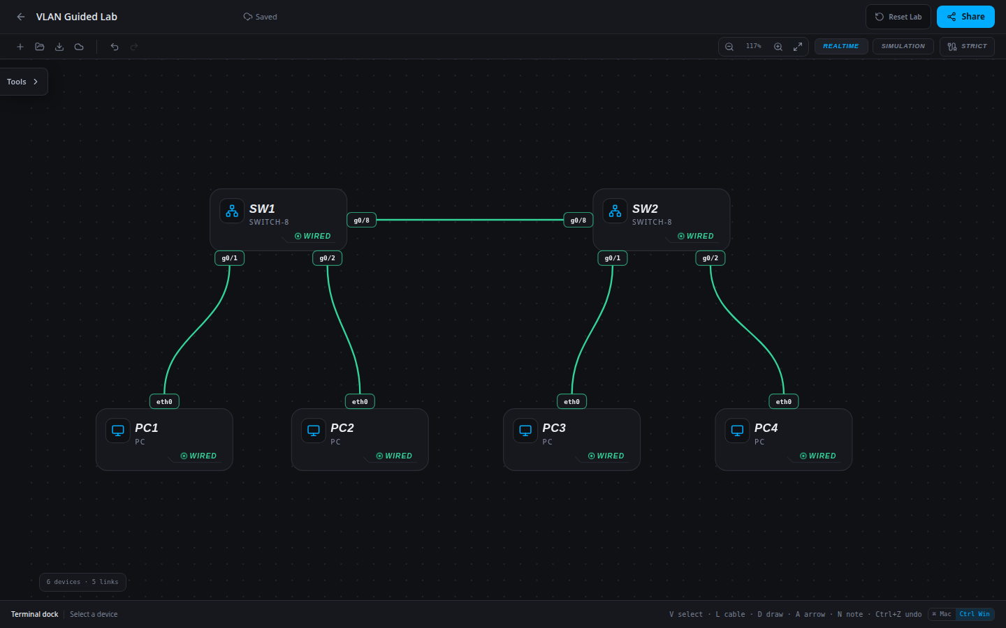
6 devices · 5 links
Scenario
A training centre has two wiring closets. Students and staff use both closets. Configure VLAN 10 for STUDENTS and VLAN 20 for STAFF, and carry both over one interswitch trunk.
Objectives
- Create VLANs 10 and 20 on both switches.
- Assign each host-facing port to its department.
- Carry both VLANs on the trunk and prove same-VLAN reachability.
- Explain why different VLANs still need a router to communicate.
CCNA blueprint
200-301 v1.1 objectives — this lab covers the following specific skills, not every subtopic in the domain.
- 2.1.a — Data access-port VLAN assignment across two switches (voice VLAN is outside this lab).
- 2.2.a — Trunk ports carrying multiple VLANs.
- 2.2.b — 802.1Q VLAN tagging on the interswitch link.
Starting information
- SW1 and SW2 each use g0/1 for a student PC, g0/2 for a staff PC, and g0/8 for the interswitch link.
- PC1 and PC3 are students; PC2 and PC4 are staff. The addressing and cable tables below are authoritative.
- All switch ports begin in VLAN 1. No router or default gateway is configured. Physical link-up alone does not prove correct segmentation.
- Before configuration, same-subnet student PCs can already ping through VLAN 1. Success means both correct VLAN/trunk state and connectivity, not merely a successful ping.
| Host | IPv4 address | Mask | Gateway |
|---|---|---|---|
| PC1 | 192.168.10.10 | 255.255.255.0 | None |
| PC2 | 192.168.20.20 | 255.255.255.0 | None |
| PC3 | 192.168.10.30 | 255.255.255.0 | None |
| PC4 | 192.168.20.40 | 255.255.255.0 | None |
| Device / port | Device / port |
|---|---|
| PC1 / eth0 | SW1 / g0/1 |
| PC2 / eth0 | SW1 / g0/2 |
| SW1 / g0/8 | SW2 / g0/8 |
| PC3 / eth0 | SW2 / g0/1 |
| PC4 / eth0 | SW2 / g0/2 |
Tasks
- Open SW1, select CLI, and enter
enable, thenconfigure terminal. Createvlan 10,name STUDENTS, exit; createvlan 20,name STAFF, exit. Repeat on SW2. - On SW1 enter
interface g0/1,switchport mode access,switchport access vlan 10, then exit. Assign g0/2 to VLAN 20 with the same command pattern. Repeat on SW2. - On each switch select
interface g0/8, enterswitchport mode trunkandswitchport trunk allowed vlan 10,20, then end. Leave the native VLAN at its default. - Predict which peers should communicate. Run the show commands and all endpoint checks below. Save both switch configurations with
copy running-config startup-config.
Useful commands
enable
configure terminal
vlan 10
name STUDENTS
interface g0/1
switchport mode access
switchport access vlan 10
switchport mode trunk
switchport trunk allowed vlan 10,20
show vlan brief
show interfaces trunk
copy running-config startup-config
Progressive hints
Hint 1
Compare each PC’s department with the VLAN of its directly connected port. Link-up only proves the cable is usable.
Hint 2
A VLAN must exist on both switches. The interswitch port must carry tagged traffic for both VLANs.
Hint 3
Use show vlan brief for g0/1 and g0/2 membership, then show interfaces trunk for g0/8 and the allowed VLAN list. Configure both ends.
Verification
- On both switches,
show vlan brieflists STUDENTS (10) with g0/1 and STAFF (20) with g0/2. - On both switches,
show interfaces trunkshows g0/8 trunking and VLANs 10,20 allowed. - PC1 → 192.168.10.30 and PC3 → 192.168.10.10 succeed. PC2 → 192.168.20.40 and PC4 → 192.168.20.20 succeed.
- PC1 → 192.168.20.20 fails because there is no inter-VLAN router. This negative control alone does not prove VLAN membership; inspect the switch tables too.
Solution / walkthrough
Show Solution
Use enable only from a > prompt; if already at #, begin with configure terminal.
SW1
Create the two VLANs, assign the edge ports, and allow both VLANs on the trunk. Save the working configuration.
enable
configure terminal
vlan 10
name STUDENTS
exit
vlan 20
name STAFF
exit
interface g0/1
switchport mode access
switchport access vlan 10
exit
interface g0/2
switchport mode access
switchport access vlan 20
exit
interface g0/8
switchport mode trunk
switchport trunk allowed vlan 10,20
end
copy running-config startup-config
SW2
Create the two VLANs, assign the edge ports, and allow both VLANs on the trunk. Save the working configuration.
enable
configure terminal
vlan 10
name STUDENTS
exit
vlan 20
name STAFF
exit
interface g0/1
switchport mode access
switchport access vlan 10
exit
interface g0/2
switchport mode access
switchport access vlan 20
exit
interface g0/8
switchport mode trunk
switchport trunk allowed vlan 10,20
end
copy running-config startup-config
Run every verification check above after the changes. A saved configuration alone does not prove packet delivery.