Static routes scale to about three routers before they stop being fun. Past that, every new subnet means logging into every router and adding another line — and forgetting one means a black hole that takes 20 minutes to find. Dynamic routing exists so the routers learn the topology themselves and adapt when something changes.
OSPF (Open Shortest Path First) is the link-state IGP the CCNA exam centres on. Each router builds a complete map of the area, runs Dijkstra's algorithm against it, and installs the shortest path to every known network. When a link dies, every router in the area is told within seconds and the table reconverges — no waiting, no manual intervention.
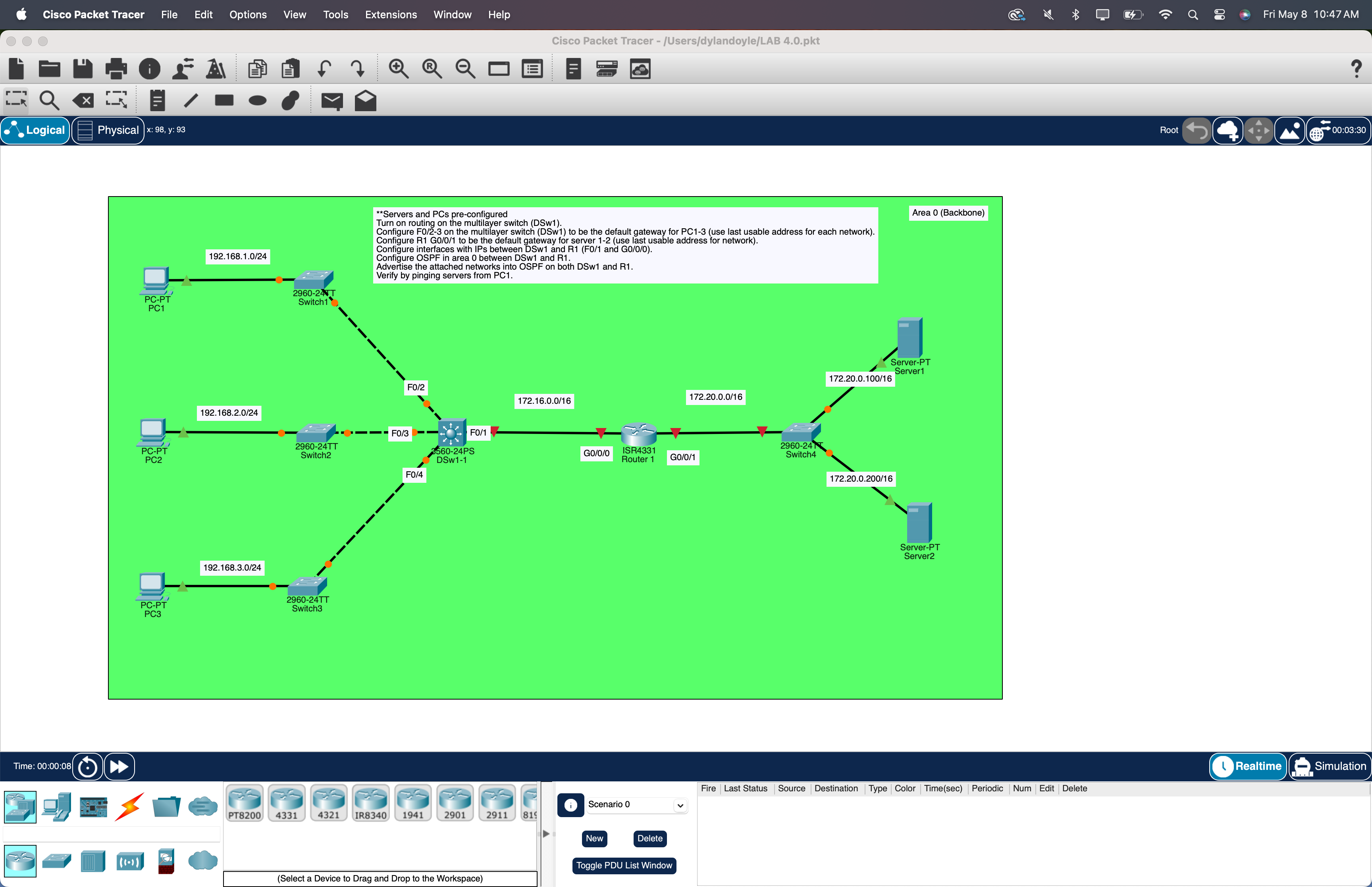
This lab stands up OSPFv2 single-area (area 0) across a multilayer switch and one router in Packet Tracer. Four LANs get advertised: three PC segments hanging off the layer-3 switch, one /16 server segment off the router. When it's working, a ping from PC1 to a server in the 172.20.0.0/16 LAN traverses two devices it has never been told about — and just works.
★ WHY OSPF / IS-IS
OSPF and IS-IS are the two link-state IGPs that run real networks. Different mechanics under the hood — IS-IS rides directly on layer 2, OSPF on IP — but the algorithm (Dijkstra) and the design philosophy are the same. Almost every enterprise network uses one. Almost every ISP backbone uses the other. The CCNA tests OSPF, but the moment you understand it, IS-IS is a weekend's worth of vocabulary away.
Distance-vector (RIP, EIGRP)
Routers gossip their tables. "I can reach 192.168.1.0 in 3 hops, ask me." Nobody ever sees the full map — they trust their neighbour's summary.
Link-state (OSPF, IS-IS)
Every router floods a description of its own links. Every router builds the same complete map, then independently runs Dijkstra and picks shortest paths. Faster convergence, loop-free by construction, scales to thousands of devices via areas.
★ KEY OSPF CONCEPTS — ALL TESTED
Five vocabulary items show up on every OSPF question. Worth pinning before you touch the CLI.
Locally significant. router ospf 1 on one router and router ospf 99 on another still form a neighbourship. Don't confuse it with AS or area number.
A 32-bit identifier in dotted-decimal. Manually pinned, or auto-picked from the highest loopback, then highest physical interface. Always pin it manually so it stays predictable across reboots.
Administrative grouping for LSDB scope. Single-area means everything sits in area 0 (the backbone). Multi-area is a Day-2 design topic — out of scope here.
Inverse of a subnet mask. Subtract each octet from 255.
/30 → 0.0.0.3
/29 → 0.0.0.7
/28 → 0.0.0.15
/24 → 0.0.0.255
/16 → 0.0.255.255
Two OSPF speakers that have exchanged Hello packets, agreed on parameters, and synced their LSDBs. Healthy state = FULL. Anything else means broken.
★ IP ADDRESSING TABLE
| DEVICE | INTERFACE | IP / MASK | ROLE |
|---|---|---|---|
| DSW | Fa0/1 (no switchport) | 172.16.0.1/16 | ↔ R1 g0/0/0 |
| DSW | Fa0/2 (no switchport) | 192.168.1.254/24 | GW for PC1 |
| DSW | Fa0/3 (no switchport) | 192.168.2.254/24 | GW for PC2 |
| DSW | Fa0/4 (no switchport) | 192.168.3.254/24 | GW for PC3 |
| R1 | Gi0/0/0 | 172.16.0.2/16 | ↔ DSW Fa0/1 |
| R1 | Gi0/0/1 | 172.20.255.254/16 | GW for servers |
| PC1 | NIC | 192.168.1.10/24 GW 192.168.1.254 | DSW Fa0/2 LAN |
| PC2 | NIC | 192.168.2.10/24 GW 192.168.2.254 | DSW Fa0/3 LAN |
| PC3 | NIC | 192.168.3.10/24 GW 192.168.3.254 | DSW Fa0/4 LAN |
| Server1 | NIC | 172.20.0.100/16 GW 172.20.255.254 | R1 Gi0/0/1 LAN |
| Server2 | NIC | 172.20.0.200/16 GW 172.20.255.254 | R1 Gi0/0/1 LAN |
Every host-side LAN uses the last usable address as the gateway — .254 on the /24 PC LANs, .255.254 on the /16 server segment. A common convention — easy to remember and leaves the low addresses for static infrastructure.
★ STEP 1 — DSW (THE MULTILAYER SWITCH)
DSW is the layer-3 boundary for the user side. It has no VLANs in this lab — instead, every PC-facing port is a routed (no switchport) interface with its own /24, and the uplink to R1 is another routed port on a /16. ip routing turns the box from a switch into a switch-with-routing.
A routed port behaves like a router interface — it has an IP, it doesn't participate in VLANs, and you can't trunk it. If you ever need it back as an L2 port, switchport on the interface flips it back.
★ STEP 2 — R1 (THE ROUTER)
One router with two interfaces. Gi0/0/0 faces DSW, Gi0/0/1 faces the server segment.
Sanity-check the L1/L2/IP layer before turning on OSPF.
If either ping fails, fix that first — OSPF will never come up over a broken link.
★ STEP 3 — TURN ON OSPF
Two devices run OSPF: DSW and R1. Each gets a process number, a router-ID, and a list of which directly-connected networks to advertise into area 0.
WHAT EACH PIECE DOES
Starts an OSPF process. The "1" is the process ID — locally significant, doesn't have to match across devices.
Pins the router's identity. Without this, IOS picks the highest interface IP, which can drift if you bring an interface up or down. Pinning keeps the LSDB stable.
"Any of my interfaces falling inside this range — send Hellos out and advertise into area 0." The wildcard mask matches the interface IP.
0.0.0.255 matches a /240.0.255.255 matches a /16
Keeps advertising the network into OSPF, but stops sending Hello packets out that interface. PCs and servers don't speak OSPF, so silencing host-facing ports saves CPU and shaves the attack surface (BPDUs / Hellos shouldn't leak onto user LANs).
★ STEP 4 — VERIFY THE ADJACENCY
Within seconds of OSPF coming up on both sides, you should see a neighbour-up console message. Confirm it.
One link, one adjacency from each side. Both should sit at FULL.
INIT
One side is hearing Hellos, the other isn't replying. Check the network statement and wildcard mask on the silent side.
EXSTART / EXCHANGE
Adjacency stuck during the database descriptor exchange. Almost always an MTU mismatch — or duplicate router-IDs. Run show ip ospf interface on both ends and compare MTU.
2-WAY ONLY
Expected on a multi-access segment for non-DR/BDR routers. On a point-to-point link like this one, it indicates a problem.
★ STEP 5 — VERIFY THE ROUTING TABLES
Each device should have learned every network it isn't directly connected to. Routes show up tagged O (intra-area OSPF).
110 is OSPF's administrative distance — same on every Cisco router. The number after the slash is the cost (default = 100M / interface bandwidth, accumulated along the path).
★ STEP 6 — END-TO-END VERIFICATION
The whole point. From PC1, ping each server.
Repeat from PC2 and PC3, then trace the path to confirm OSPF picked the route you expect.
No static routes were configured anywhere. DSW learned the server segment from R1; R1 learned the three PC LANs from DSW. Plug in a fifth LAN tomorrow, advertise it, and the other device knows about it within seconds — no touching anything else.
★ THINGS WORTH TRIGGERING
This topology has a single path between the two ends, so dramatic reconvergence demos aren't on the menu — for that, see Lab 4 (RSTP) on the L2 side, or extend this lab with a second router. What you can still poke at:
From DSW, interface fa0/1 + shutdown. Adjacency drops, both routing tables lose their OSPF entries within seconds. no shutdown brings them back. Watch show ip ospf neighbor in real time.
ip ospf cost 50 on an interface, then re-check show ip route ospf. The metric changes; the path doesn't (only one option). Useful to see how cost propagates in LSAs.
no router-id 1.1.1.1 on R1, then commit a new ID and run clear ip ospf process. Adjacency tears down and re-forms — useful for seeing how the LSDB rebuilds from scratch.
ip ospf hello-interval 5 on one side of the link only. Adjacency drops and won't re-form — Hello/Dead agreement is mandatory. Restore symmetry to bring it back. Common real-world bug, worth experiencing once.
Drop a second router (R2) between R1 and the server segment, give it a /16 link to R1, and bring it into area 0. Now you have a real multi-router LSDB and can trigger genuine reconvergence by shutting the R1↔R2 link.
★ COMMON GOTCHAS
Symptom: Each PC can ping its own gateway and other PCs on the same /24, but nothing else. OSPF won't even start.
Fix: ip routing in global config on DSW. The 3560 needs this to forward between L3 interfaces.
Symptom: Adjacency never forms. No console message. show ip ospf interface brief shows the interface as not running OSPF.
Cause: Typed a subnet mask in the network statement instead of a wildcard. 255.255.0.0 doesn't match anything; 0.0.255.255 matches the /16. IOS accepts both syntactically — it just silently matches nothing.
Fix: Subtract each octet from 255 before typing.
Symptom: OSPF runs on the link itself, but a LAN behind one of your interfaces never appears in the other device's routing table.
Fix: show ip protocols lists every active network statement on the device. Cross-reference against your interfaces — every IP that should be in OSPF must be matched by exactly one network statement.
Symptom: Neighbour state oscillates between EXSTART and EXCHANGE forever. Never reaches FULL.
Cause: The two ends disagree on IP MTU. The DBD packet exchange refuses to complete on a mismatch.
Fix: ip ospf mtu-ignore on the interface (lab-grade fix), or set the actual MTU equal on both sides (production fix).
★ VERIFICATION CHEAT SHEET
★ LAB DOWNLOAD
Built and tested in Packet Tracer 8.x. PCs and servers ship pre-addressed; routing config is yours to build. Run the steps in order and you'll have OSPF up in roughly 15 minutes.
Pre-addressed PCs and servers, OSPF config is yours to build ⬇ DOWNLOAD .PKT
The OCG Library (Vol 1 + Vol 2) covers OSPF in Vol 1 chapters 21-24 — the textbook companion to this lab. If you want to run it on real gear, pair a 2960X with a USB console cable. Amazon affiliates.