Open the lab
[ YOUR LAB FILE ]
Download the starting topology, then work through the lesson in SwitchLab.
- Save the .swlab file without renaming its extension.
- Open SwitchLab. Import and export controls currently require a desktop-width window. On a smaller screen, Tools → Fit brings the topology into view.
- Select Import Sandbox (folder icon), choose the downloaded file, and confirm the device and cable counts below.
- Select a device, then choose Open device on desktop or its name in the bottom bar on smaller screens. Select CLI for switches/routers or Desktop → Terminal for PCs. Enter
enableonly when the prompt ends in >. - Follow this page beside the simulator. Use a free account to export your work. Reimport the original download to restart; export any work you want to keep first.
Prerequisites
- Complete the Ethernet fundamentals lessons.
- For the routed troubleshooting lessons, recognize connected and static routes.
Topology
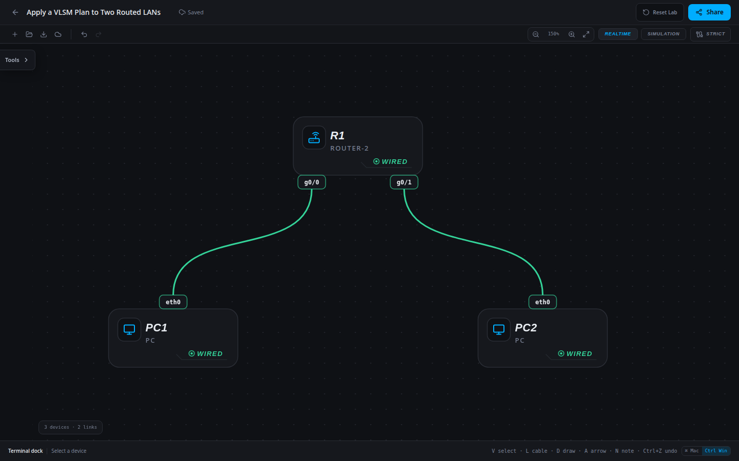
3 devices · 2 links
Scenario
A branch has 25 office hosts and 10 workshop hosts. Its allocation is 172.16.40.0/24. The representative PCs already follow the approved largest-first plan; configure R1 so the two LANs can communicate.
Objectives
- Derive or verify IPv4 host and gateway settings against the approved subnet plan.
- Prove the intended local and routed paths after correcting configuration.
CCNA blueprint
200-301 v1.1 objectives — this lab covers the following specific skills, not every subtopic in the domain.
- 1.6 — Configure and verify IPv4 addressing and subnetting.
Starting information
- Allocate the lowest available subnet for 25 office hosts first, then the next available subnet for 10 workshop hosts. Reserve the first usable address of each subnet for its gateway.
- Office PC1 is on R1 g0/0; Workshop PC2 is on g0/1. Host addresses and masks are already correct.
- R1 routes both directly connected LANs; no default route or static route is required.
| Host | IPv4 address | Mask | Gateway |
|---|---|---|---|
| PC1 | 172.16.40.10 | 255.255.255.224 | 172.16.40.1 |
| PC2 | 172.16.40.34 | 255.255.255.240 | 172.16.40.33 |
| Device / port | Device / port |
|---|---|
| PC1 / eth0 | R1 / g0/0 |
| PC2 / eth0 | R1 / g0/1 |
Tasks
- Calculate the smallest prefix for each host count, then derive both subnet ranges and gateways.
- Configure R1 g0/0 and g0/1 with those gateway addresses and masks, keeping both interfaces enabled.
- Inspect
show ip interface briefandshow ip route. Match each connected route to its allocated subnet. - Ping in both directions between PC1 and PC2 and explain why these two subnets do not overlap. Save and export the result.
Useful commands
show ip interface brief
show ip route
copy running-config startup-config
Progressive hints
Hint 1
Calculate the subnet boundary before changing an address. A gateway is used only for a destination outside the host subnet.
Hint 2
Compare all three settings—address, mask and gateway. A successful ping alone may not reveal an overly broad mask.
Hint 3
Use the first usable address for each requested gateway; for PC repairs, apply netsh ip set with the exact approved address, mask and gateway.
Verification
- The final addressing matches the approved plan exactly.
- All paths listed in the tasks succeed in both directions.
- The completed export retains the repaired addressing after reload.
Solution / walkthrough
Show Solution
Use enable only from a > prompt; if already at #, begin with configure terminal.
R1
The /27 uses .0–.31 with usable .1–.30; the /28 uses .32–.47 with usable .33–.46. The router installs both connected routes when its interfaces are addressed and up.
enable
configure terminal
interface g0/0
ip address 172.16.40.1 255.255.255.224
no shutdown
exit
interface g0/1
ip address 172.16.40.33 255.255.255.240
no shutdown
end
copy running-config startup-config
Run every verification check above after the changes. A saved configuration alone does not prove packet delivery.