Open the lab
[ YOUR LAB FILE ]
Download the starting topology, then work through the lesson in SwitchLab.
- Save the .swlab file without renaming its extension.
- Open SwitchLab. Import and export controls currently require a desktop-width window. On a smaller screen, Tools → Fit brings the topology into view.
- Select Import Sandbox (folder icon), choose the downloaded file, and confirm the device and cable counts below.
- Select a device, then choose Open device on desktop or its name in the bottom bar on smaller screens. Select CLI for switches/routers or Desktop → Terminal for PCs. Enter
enableonly when the prompt ends in >. - Follow this page beside the simulator. Use a free account to export your work. Reimport the original download to restart; export any work you want to keep first.
Prerequisites
- Complete trunking and STP fundamentals.
Topology
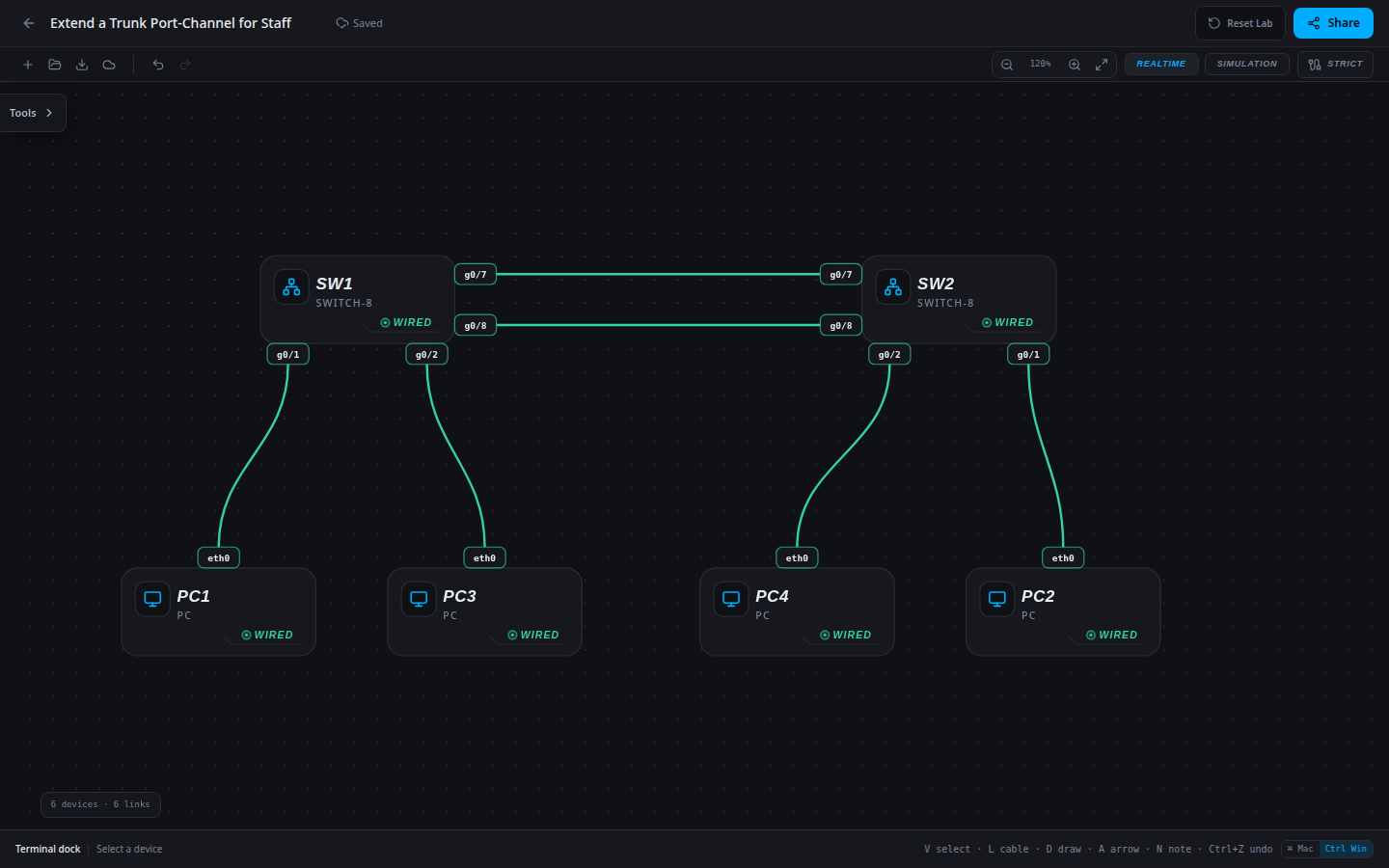
6 devices · 6 links
Scenario
The existing LACP trunk carries Users VLAN 10. A Staff expansion needs VLAN 20 across the same logical uplink; the Staff access ports and addresses are already correct.
Objectives
- Verify LACP negotiation and the state of both member ports.
- Retain required VLAN traffic through the logical bundle and after a member outage.
CCNA blueprint
200-301 v1.1 objectives — this lab covers the following specific skills, not every subtopic in the domain.
- 2.4 — Configure and verify Layer 2 EtherChannel using LACP.
Starting information
- SW1 g0/7 and g0/8 connect to matching ports on SW2. Bundle both in channel-group 1.
- Approved LACP roles: SW1 active, SW2 passive. The completed logical trunk carries VLANs 10,20 with matching native VLANs.
- PC1/PC2 are Users VLAN 10; PC3/PC4 are Staff VLAN 20. Do not change their addresses or access memberships.
- This lab verifies negotiation, member state and delivery; it does not measure aggregated bandwidth or promise a particular per-flow load-balancing result.
| Host | IPv4 address | Mask | Gateway |
|---|---|---|---|
| PC1 | 192.168.10.10 | 255.255.255.0 | None |
| PC2 | 192.168.10.20 | 255.255.255.0 | None |
| PC3 | 192.168.20.30 | 255.255.255.0 | None |
| PC4 | 192.168.20.40 | 255.255.255.0 | None |
| Device / port | Device / port |
|---|---|
| SW1 / g0/7 | SW2 / g0/7 |
| SW1 / g0/8 | SW2 / g0/8 |
| PC1 / eth0 | SW1 / g0/1 |
| PC2 / eth0 | SW2 / g0/1 |
| PC3 / eth0 | SW1 / g0/2 |
| PC4 / eth0 | SW2 / g0/2 |
Tasks
- Inspect
show etherchannel summary, trunk output and both member configurations before making a change. - Apply the approved LACP roles and VLAN policy on the required member and port-channel interfaces. Avoid mixing a static channel with LACP.
- Verify Po1 is a Layer 2 channel in use and both g0/7 and g0/8 show the bundled P flag on each switch.
- Ping Users and Staff in both directions. Shut g0/7 on both ends, confirm Po1 remains up with g0/8 bundled, and repeat traffic. Restore both interfaces, verify two members again and export.
Useful commands
show etherchannel summary
show interfaces trunk
show running-config
copy running-config startup-config
Progressive hints
Hint 1
Read the channel summary flags before assuming two connected cables are a working bundle.
Hint 2
LACP passive responds but does not initiate. At least one side needs active mode, and member trunk settings must agree.
Hint 3
Configure SW1 active and SW2 passive in channel-group 1; inspect both members and the logical port-channel VLAN policy.
Verification
- Both switches show Po1(SU) with LACP and both member ports bundled after restoration.
- Users and Staff communicate in both directions.
- With g0/7 disabled at both ends, Po1 remains operational through g0/8 and required traffic still succeeds.
Solution / walkthrough
Show Solution
Use enable only from a > prompt; if already at #, begin with configure terminal.
SW1
Use compatible member settings and an active LACP initiator. Preserve the host access VLANs; verify both members, not just the existence of Po1.
enable
configure terminal
interface g0/7
switchport mode trunk
switchport trunk allowed vlan 10,20
channel-group 1 mode active
exit
interface g0/8
switchport mode trunk
switchport trunk allowed vlan 10,20
channel-group 1 mode active
exit
interface port-channel 1
switchport mode trunk
switchport trunk allowed vlan 10,20
exit
end
copy running-config startup-config
SW2
Use compatible member settings and an active LACP initiator. Preserve the host access VLANs; verify both members, not just the existence of Po1.
enable
configure terminal
interface g0/7
switchport mode trunk
switchport trunk allowed vlan 10,20
channel-group 1 mode passive
exit
interface g0/8
switchport mode trunk
switchport trunk allowed vlan 10,20
channel-group 1 mode passive
exit
interface port-channel 1
switchport mode trunk
switchport trunk allowed vlan 10,20
exit
end
copy running-config startup-config
Run every verification check above after the changes. A saved configuration alone does not prove packet delivery.