Open the lab
[ YOUR LAB FILE ]
Download the starting topology, then work through the lesson in SwitchLab.
- Save the .swlab file without renaming its extension.
- Open SwitchLab. Import and export controls currently require a desktop-width window. On a smaller screen, Tools → Fit brings the topology into view.
- Select Import Sandbox (folder icon), choose the downloaded file, and confirm the device and cable counts below.
- Select a device, then choose Open device on desktop or its name in the bottom bar on smaller screens. Select CLI for switches/routers or Desktop → Terminal for PCs. Enter
enableonly when the prompt ends in >. - Follow this page beside the simulator. Use a free account to export your work. Reimport the original download to restart; export any work you want to keep first.
Prerequisites
- Complete VLAN Guided Lab and distinguish VLAN membership from IP addressing.
Topology
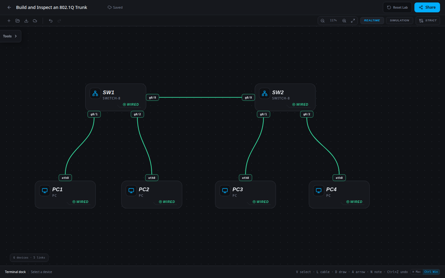
6 devices · 5 links
Scenario
The access VLANs are ready in both closets, but the connecting switch ports still operate as access ports in VLAN 1. Bring both departments across the shared uplink.
Objectives
- Translate the approved VLAN plan into switch configuration.
- Verify port membership and every trunk in the path.
- Preserve working traffic while proving the new department or uplink.
CCNA blueprint
200-301 v1.1 objectives — this lab covers the following specific skills, not every subtopic in the domain.
- 2.1.a — Configure data access VLANs.
- 2.2.a — Configure trunk ports and restricted VLAN carriage.
- 2.2.b — Use 802.1Q VLAN separation across switches.
Starting information
- VLANs 10 STUDENTS and 20 STAFF already exist with correct access ports and host addresses.
- SW1 g0/8 connects to SW2 g0/8. Configure both as trunks with allowed VLANs 10,20. Keep the native VLAN at its matching default on both ends.
| Host | IPv4 address | Mask | Gateway |
|---|---|---|---|
| PC1 | 192.168.10.10 | 255.255.255.0 | None |
| PC2 | 192.168.20.20 | 255.255.255.0 | None |
| PC3 | 192.168.10.30 | 255.255.255.0 | None |
| PC4 | 192.168.20.40 | 255.255.255.0 | None |
| Device / port | Device / port |
|---|---|
| PC1 / eth0 | SW1 / g0/1 |
| PC2 / eth0 | SW1 / g0/2 |
| SW1 / g0/8 | SW2 / g0/8 |
| PC3 / eth0 | SW2 / g0/1 |
| PC4 / eth0 | SW2 / g0/2 |
Tasks
- Test Student and Staff traffic between closets, then inspect
show interfaces trunkand both g0/8 configurations. - On each switch enter
configure terminal, selectinterface g0/8, setswitchport mode trunkandswitchport trunk allowed vlan 10,20, thenend. - Run
show interfaces trunkon both switches; identify the operational trunk and allowed VLAN list. - Repeat both departmental paths in both directions. Save/export the network and explain how a tagged trunk differs from a single-VLAN access port.
Useful commands
show vlan brief
show interfaces trunk
copy running-config startup-config
Progressive hints
Hint 1
Separate VLAN existence, access-port assignment and trunk carriage when diagnosing the path.
Hint 2
Every switch carrying a VLAN needs that VLAN locally, and both ends of every transit link need compatible trunk policy.
Hint 3
Use show running-config interface for the affected port; compare switchport access vlan on host ports and switchport trunk allowed vlan on uplinks against the approved plan.
Verification
- VLANs 10 STUDENTS and 20 STAFF already exist with correct access ports and host addresses.
- SW1 g0/8 connects to SW2 g0/8. Configure both as trunks with allowed VLANs 10,20. Keep the native VLAN at its matching default on both ends.
- Student and Staff paths succeed in both directions; configuration output matches the required membership and trunk policy.
Solution / walkthrough
Show Solution
Use enable only from a > prompt; if already at #, begin with configure terminal.
SW1
Make both ends of the interswitch cable trunks carrying the two existing access VLANs.
enable
configure terminal
interface g0/8
switchport mode trunk
switchport trunk allowed vlan 10,20
end
copy running-config startup-config
SW2
Make both ends of the interswitch cable trunks carrying the two existing access VLANs.
enable
configure terminal
interface g0/8
switchport mode trunk
switchport trunk allowed vlan 10,20
end
copy running-config startup-config
Run every verification check above after the changes. A saved configuration alone does not prove packet delivery.