Open the lab
[ YOUR LAB FILE ]
Download the starting topology, then work through the lesson in SwitchLab.
- Save the .swlab file without renaming its extension.
- Open SwitchLab. Import and export controls currently require a desktop-width window. On a smaller screen, Tools → Fit brings the topology into view.
- Select Import Sandbox (folder icon), choose the downloaded file, and confirm the device and cable counts below.
- Select a device, then choose Open device on desktop or its name in the bottom bar on smaller screens. Select CLI for switches/routers or Desktop → Terminal for PCs. Enter
enableonly when the prompt ends in >. - Follow this page beside the simulator. Use a free account to export your work. Reimport the original download to restart; export any work you want to keep first.
Prerequisites
- Complete Build Your First OSPF Neighbor Relationship and Advertise LANs over an Existing OSPF Link.
- Read a next hop from an OSPF route and distinguish a transit subnet from a user LAN.
Topology
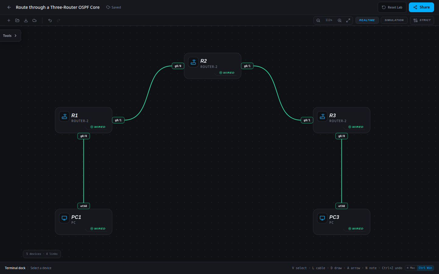
5 devices · 4 links
Scenario
Two regional offices connect through a core router that has no workstation LAN of its own. The addresses and physical circuits are ready. Deploy one OSPF area and prove that the core can forward both user traffic and its replies between the edge routers.
Objectives
- Identify which interfaces need neighbors based on their topology role rather than their port number.
- Deploy OSPF across both core links with unique router IDs.
- Trace learned LAN routes across R2 and verify end-to-end traffic in both directions.
CCNA blueprint
200-301 v1.1 objectives — this lab covers the following specific skills, not every subtopic in the domain.
- 3.4.a — Troubleshoot single-area OSPFv2 neighbor adjacency.
- 3.4.d — Identify peers by router ID.
- 3.1.a — Distinguish OSPF-learned routes from connected routes.
Starting information
- R1 serves 10.10.10.0/24, R3 serves 10.30.30.0/24, and R2 connects their transit links. All addresses and enabled interfaces are shown below.
- Use OSPF process 1 and area 0 everywhere. Assign IDs 1.1.1.1, 2.2.2.2 and 3.3.3.3 to R1, R2 and R3 respectively.
- No routing process or static route is present initially. Only R1 g0/0 and R3 g0/0 are user LAN interfaces; both should be passive. R2 g0/0 is a transit interface and must remain active.
| Host | IPv4 address | Mask | Gateway |
|---|---|---|---|
| PC1 | 10.10.10.10 | 255.255.255.0 | 10.10.10.1 |
| PC3 | 10.30.30.30 | 255.255.255.0 | 10.30.30.1 |
| Router | Interface | IPv4 address | Mask |
|---|---|---|---|
| R1 | g0/0 | 10.10.10.1 | 255.255.255.0 |
| R1 | g0/1 | 10.0.12.1 | 255.255.255.252 |
| R2 | g0/0 | 10.0.12.2 | 255.255.255.252 |
| R2 | g0/1 | 10.0.23.1 | 255.255.255.252 |
| R3 | g0/0 | 10.30.30.1 | 255.255.255.0 |
| R3 | g0/1 | 10.0.23.2 | 255.255.255.252 |
| Device / port | Device / port |
|---|---|
| PC1 / eth0 | R1 / g0/0 |
| R1 / g0/1 | R2 / g0/0 |
| R2 / g0/1 | R3 / g0/1 |
| PC3 / eth0 | R3 / g0/0 |
Tasks
- Predict the number of OSPF peers on each router. Explain why the core needs two peers while each edge needs one.
- Configure the specified IDs and advertise every connected transit and user subnet in area 0. Use specific /30 and /24 wildcard matches.
- Suppress neighbor exchanges only on user LANs. Do not copy the edge passive-interface setting blindly onto R2 g0/0.
- Inspect R2’s two neighbors and both remote LAN routes. On each edge, identify the adjacent next hop and explain why the far edge router is not the next hop.
- Test both workstation directions. Record each hop’s forwarding and return decision, then save all three router configurations.
Useful commands
show ip interface brief
show ip ospf neighbor
show ip ospf interface brief
show ip route
show running-config
copy running-config startup-config
Progressive hints
Hint 1
Draw the path from PC1 to PC3 before configuring a routing process. Each transit router must know both LAN destinations.
Hint 2
R2 has two router-facing interfaces. A passive setting appropriate for an edge g0/0 would break this core link.
Hint 3
R2 needs area-0 statements for 10.0.12.0/30 and 10.0.23.0/30. Verify neighbors 1.1.1.1 and 3.3.3.3 before testing the far LAN.
Verification
- Initially the local gateways work but the far workstation does not.
- R2 has FULL neighbors 1.1.1.1 and 3.3.3.3, and learns both 10.10.10.0/24 and 10.30.30.0/24.
- R1 learns the remote LAN via 10.0.12.2; R3 learns the HQ LAN via 10.0.23.1.
- PC1 → 10.30.30.30 and PC3 → 10.10.10.10 succeed. Only workstation-facing interfaces are passive.
Solution / walkthrough
Show Solution
Use enable only from a > prompt; if already at #, begin with configure terminal.
R1
Enable all connected transit subnets in area 0. Advertise the user LAN while keeping its interface passive.
enable
configure terminal
router ospf 1
router-id 1.1.1.1
network 10.10.10.0 0.0.0.255 area 0
network 10.0.12.0 0.0.0.3 area 0
passive-interface g0/0
end
copy running-config startup-config
R2
Enable all connected transit subnets in area 0. Both interfaces face router peers, so neither should be passive.
enable
configure terminal
router ospf 1
router-id 2.2.2.2
network 10.0.12.0 0.0.0.3 area 0
network 10.0.23.0 0.0.0.3 area 0
end
copy running-config startup-config
R3
Enable all connected transit subnets in area 0. Advertise the user LAN while keeping its interface passive.
enable
configure terminal
router ospf 1
router-id 3.3.3.3
network 10.30.30.0 0.0.0.255 area 0
network 10.0.23.0 0.0.0.3 area 0
passive-interface g0/0
end
copy running-config startup-config
Run every verification check above after the changes. A saved configuration alone does not prove packet delivery.