OSPF in one area scales to maybe a few dozen routers before the LSDB, SPF runtime, and flooding scope all start to bite at once. The fix is areas: partition the domain so each router only carries the topology of its own area, plus condensed inter-area summaries from the ABRs. This lab is a deliberate "minimum to learn" build — four leaf areas, one backbone, and just enough routers to make every CCNA-level concept visible in the LSDB.
The lab also runs two distinct OSPF configuration styles side by side. R10/R20/R30 advertise their interfaces using classic network statements under router ospf — the way Jeremy's IT Lab and the OCG teach it. R40 uses ip ospf 1 area 4 directly on each interface — the modern best practice, no wildcards to mis-type, area selection right next to the interface it applies to. Compare the two and decide which one you'd reach for at work.
★ WHY MULTI-AREA EXISTS
Single-area OSPF gives you three problems at scale, and multi-area solves all three at once:
In one area, every router holds an identical copy of every link in the domain. In multi-area, each router only holds the type-1/type-2 LSAs for its own area, plus condensed type-3 summary LSAs from the ABRs. Less memory, less SPF input, faster convergence on a link flap.
A link flap in area 1 floods type-1 LSAs only inside area 1. The ABR re-originates a type-3 summary into area 0 (and the other areas) only if the summary itself changed — most internal flaps never leave the area at all. Sitewide flooding goes away.
SPF is O(n log n) on the area's link count. Cutting the area's size cuts the runtime — and SPF runs on every router for every topology change in its area. On a 500-router single-area domain, that adds up fast; in multi-area, most routers never even see the change.
Area 0 always exists, and every other area must touch area 0. A non-backbone area connected only to another non-backbone area is invisible from the rest of the domain. (You can fake it with a virtual link, but that's a workaround, not a design — and it's CCNP territory.) In this lab every ABR has a foot in area 0 by construction.
★ ROUTER ROLES IN THIS TOPOLOGY
| ROUTER | ROLE | AREAS | NOTES |
|---|---|---|---|
| R100 | Internal backbone | Area 0 only | Router-ID 100.100.100.100. Transit between R10/R20 and R200. |
| R200 | Internal backbone | Area 0 only | Router-ID 200.200.200.200. Transit between R30/R40 and R100. |
| R10 | ABR | Area 0 + Area 1 | Loopback Lo0 10.10.10.10/32 drives the router-ID. |
| R20 | ABR | Area 0 + Area 2 | Loopback Lo0 20.20.20.20/32 drives the router-ID. |
| R30 | ABR | Area 0 + Area 3 | Loopback Lo0 30.30.30.30/32 drives the router-ID. |
| R40 | ABR (interface-mode) | Area 0 + Area 4 | No loopback — auto router-ID = highest interface IP. ip ospf 1 area X per interface. |
Six routers, five areas, one OSPF process number (we use 1 everywhere — process IDs are locally significant, but matching them is one less variable to track in show output). Three ABRs use the traditional network-statement style; one ABR uses interface-mode. Same end state, two different config muscles to build.
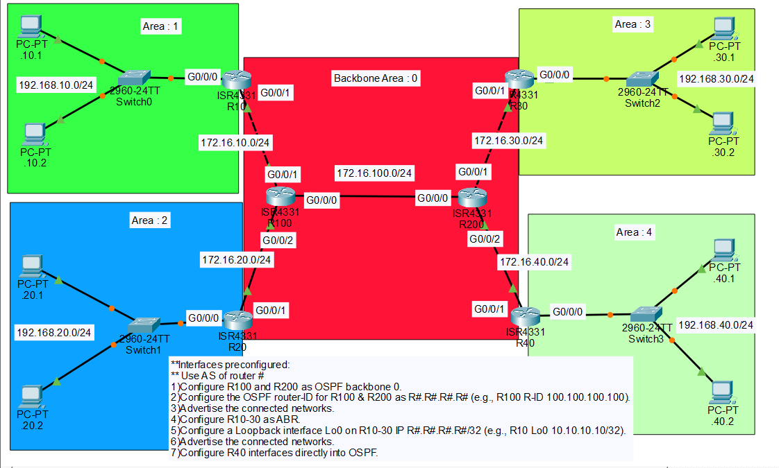
★ TOPOLOGY & ADDRESSING
The .pkt ships with every interface pre-cabled and pre-addressed — IP addresses, masks, the works. Your job is OSPF only. Open each router, confirm show ip interface brief shows the addresses below, and start at Task 1.
Convention: on the 172.16.X.0/24 transit links, each interface's last octet matches the router number — R10 G0/0/1 = 172.16.10.10, R100 G0/0/1 = 172.16.10.100, and so on. On the 192.168.X0.0/24 LANs, the router uses .254 as the gateway, matching the PCs' pre-configured default gateway.
| DEVICE | INTERFACE | IP / NEIGHBOUR | AREA |
|---|---|---|---|
| R10 | G0/0/0 | 192.168.10.254/24 (PC LAN gw) | 1 |
| R10 | G0/0/1 | 172.16.10.10/24 ↔ R100 | 0 |
| R10 | Lo0 | 10.10.10.10/32 (router-ID) | — |
| R20 | G0/0/0 | 192.168.20.254/24 (PC LAN gw) | 2 |
| R20 | G0/0/1 | 172.16.20.20/24 ↔ R100 | 0 |
| R20 | Lo0 | 20.20.20.20/32 (router-ID) | — |
| R30 | G0/0/0 | 192.168.30.254/24 (PC LAN gw) | 3 |
| R30 | G0/0/1 | 172.16.30.30/24 ↔ R200 | 0 |
| R30 | Lo0 | 30.30.30.30/32 (router-ID) | — |
| R40 | G0/0/0 | 192.168.40.254/24 (PC LAN gw) | 4 |
| R40 | G0/0/1 | 172.16.40.40/24 ↔ R200 | 0 |
| R100 | G0/0/0 | 172.16.100.100/24 ↔ R200 | 0 |
| R100 | G0/0/1 | 172.16.10.100/24 ↔ R10 | 0 |
| R100 | G0/0/2 | 172.16.20.100/24 ↔ R20 | 0 |
| R200 | G0/0/0 | 172.16.100.200/24 ↔ R100 | 0 |
| R200 | G0/0/1 | 172.16.30.200/24 ↔ R30 | 0 |
| R200 | G0/0/2 | 172.16.40.200/24 ↔ R40 | 0 |
Every PC in the lab points its default gateway at its router's .254 — PC .10.1 → 192.168.10.254, PC .40.2 → 192.168.40.254, and so on. Once OSPF converges, any PC can ping any other PC; nothing else is needed.
★ TASK 1 — BACKBONE (R100 & R200)
R100 and R200 sit entirely inside area 0. Both routers carry transit traffic only — no LANs, no leaf areas, no loopbacks. We pin the router-IDs manually with the router-id command rather than letting OSPF auto-elect from interface IPs. Manual router-IDs are how every production deployment does it: they're stable across reboots, they don't shift when an interface flaps, and they sort cleanly in show output.
- Start the OSPF process.
router ospf 1— process number is locally significant, so it doesn't need to match across routers, but pick one and stick with it. - Set the router-ID.
router-id 100.100.100.100on R100,router-id 200.200.200.200on R200. - Advertise the connected networks into area 0. One
networkstatement per interface, wildcard mask matches the/24as0.0.0.255.
OSPF picks the router-ID once, at process start, and never changes it for the life of the process. If you forget the router-id command, configure interfaces, and only then add the router-id, the new value won't take effect until you clear ip ospf process or reload. On a single backbone router that's fine; in production you'd be flapping every adjacency on the box. Set the router-ID first.
Verify on R100 — once R20 is up (Task 2), you should see R20 as a neighbour in state FULL; on R200 you'll see R30 and R40 once they're up. For now the only adjacency is R100 ↔ R200 on 172.16.100.0/24.
★ TASK 2 — ABRs (R10, R20, R30)
Each of R10/R20/R30 has a foot in two areas: the 172.16.X0.0/24 transit to its backbone neighbour goes in area 0, the 192.168.X0.0/24 LAN goes in the corresponding non-backbone area. The loopback drives the router-ID. Same three steps, repeated with different numbers.
- Create the loopback.
interface Loopback0+ip address R.R.R.R 255.255.255.255. OSPF auto-picks the highest loopback IP as the router-ID at process start — so the loopback must exist before you start the OSPF process. - Start OSPF.
router ospf 1. No explicit router-id needed; the loopback wins automatically. - Advertise both interfaces. One
networkin area 0 (the transit), one in the leaf area (the LAN).
If you accidentally configure OSPF before the loopback, the router-ID will be the highest physical-interface IP at process-start (usually one of the 172.16 transit addresses). Fix is a quick clear ip ospf process after the loopback exists — but get the order right the first time and you skip the cleanup.
Each ABR should now show two FULL neighbours: its backbone peer (R100 or R200) on the transit link, and its LAN peer — except there are no other OSPF routers in the leaf areas, so the LAN side stays at no neighbours, network active. That's expected: the LAN is in OSPF for advertisement purposes only. Hello packets still go out the LAN-side interface, which costs almost nothing but is a great hint to turn off in production with passive-interface.
In production you'd add passive-interface G0/0/0 under router ospf 1 on each ABR. The interface stays advertised but stops sending OSPF hellos out the LAN side. Security improvement (no chance a rogue device adjacencies in), CPU win on multi-access LANs. Not required for the lab — but flip it on once everything's working to see the hellos disappear from debug ip ospf hello.
★ TASK 3 — INTERFACE-MODE OSPF (R40)
Same end state as Task 2, different config style. Instead of network statements under router ospf, R40 uses ip ospf 1 area X directly under each interface. The area is declared right next to the interface it applies to — no wildcard masks, no surprises when a future colleague mis-types a wildcard and accidentally pulls a /16 into the wrong area.
R40 doesn't get a loopback. With nothing else to fall back to, OSPF auto-picks the highest interface IP at process start as the router-ID — that's 192.168.40.254 on G0/0/0. Acceptable for the lab; a real deployment would still pin router-id manually.
- Start OSPF.
router ospf 1— nonetworkstatements, norouter-id(let it auto-pick so you can see what happens). - Tag each interface.
ip ospf 1 area 0on the backbone-facing G0/0/1,ip ospf 1 area 4on the LAN-facing G0/0/0.
Both styles produce identical OSPF behaviour. The difference is operational: network 192.168.40.0 0.0.0.255 area 4 says "any interface whose primary IP matches this wildcard, advertise into area 4" — which is powerful but easy to fat-finger. ip ospf 1 area 4 on the interface says "this interface, area 4, full stop." Cisco's docs lean toward interface-mode in current best-practice guides. Use whichever style the rest of your team uses; mix them in the same router only when you have to.
Check the router-ID after the process is up:
★ VERIFY — NEIGHBOURS, LSDB, ROUTES, PING
Four checks in order: neighbour states, LSDB contents, route table, then an end-to-end ping. If any step fails, the one before it tells you where to look.
▶ NEIGHBOUR TABLE
R100 should show three FULL neighbours (R10, R20, R200). R200 should show three FULL neighbours (R30, R40, R100). Each ABR shows one FULL neighbour (its backbone peer).
▶ LSDB — TYPE 1, 2, 3
The LSDB is where multi-area pays off. On R100 (area 0 only) you'll see type-1/type-2 LSAs for area 0, and type-3 summaries for the leaf areas — but no type-1 detail of the leaf-area internals. The ABRs hide that detail.
The summary network LSAs above are how the four leaf LANs reach each other. Each ABR re-originates a type-3 LSA into area 0 advertising "I can reach 192.168.X0.0/24 at cost N." Other ABRs flood that type-3 into their own non-zero area. The leaf-area router learns the route as O IA (OSPF inter-area).
▶ ROUTE TABLE
On R10 (area 0 + area 1), 192.168.20.0/24 and the other leaf LANs show up as O IA — OSPF inter-area, learned via type-3 summary. The local 192.168.10.0/24 is a plain C (connected). The 172.16.X0.0/24 transit links inside area 0 show as O (intra-area).
▶ END-TO-END PING
From PC .10.1 in area 1 to PC .40.1 in area 4 — the path crosses ABR R10 (area 1 → area 0), then R100, then R200, then ABR R40 (area 0 → area 4).
Four hops of OSPF routing across two ABRs and two backbone-internal routers. Every inter-area route in the path was learned from a type-3 summary LSA — that's the whole point of multi-area in one ping.
★ COMMON GOTCHAS
Symptom: A leaf area is reachable internally but no other area can reach it.
Fix: Confirm the ABR has at least one interface in area 0. show ip ospf interface brief on the ABR — you should see both areas listed. If the area-0 interface is missing or shut, the ABR can't propagate type-3 summaries.
Symptom: network statement looks right but the interface never enters OSPF — show ip ospf interface shows nothing for that interface.
Fix: Wildcard mask is the inverse of the subnet mask. /24 is 0.0.0.255 — not 255.255.255.0. A /30 would be 0.0.0.3. Easy fix: switch to interface-mode ip ospf 1 area X and skip wildcards entirely.
Symptom: You added the loopback after OSPF was already running. show ip ospf still shows the old physical-interface router-ID.
Fix: clear ip ospf process at privileged exec — IOS will prompt for confirmation, then restart the OSPF process. New router-ID picks up. Don't do this in production unless you're prepared to flap every adjacency on the box.
Symptom: Two routers on the same subnet never form an adjacency. show ip ospf neighbor is empty on both ends. debug ip ospf adj shows "mismatched area ID".
Fix: Both ends of a link must agree on the area. R10's G0/0/1 (172.16.10.10) and R100's G0/0/1 (172.16.10.100) must both be in area 0. If R10 advertised that interface in area 1 by mistake, the adjacency dies silently.
Symptom: The ABR has both areas, but show ip ospf database summary in area 0 doesn't show the leaf's 192.168.X0.0/24.
Fix: Check the LAN interface is actually up and in OSPF. show ip ospf interface G0/0/0 should show the area assignment and DR election. A shut interface = no type-1 in the leaf area = no type-3 to re-originate.
★ VERIFICATION CHEAT SHEET
★ THINGS WORTH TRIGGERING
Shut R10's G0/0/1 (the backbone-facing interface). Watch from R200's perspective — within a few seconds show ip ospf neighbor on R100 will lose 10.10.10.10, and show ip route ospf sitewide will drop the 192.168.10.0/24 route. Bring the interface back up; the type-3 LSA re-floods and the route returns.
Count entries in show ip ospf database on R10 (area 0 + area 1) versus R100 (area 0 only). The ABR sees both areas' type-1/type-2 LSAs plus the type-3 summaries. The internal backbone router sees area 0's type-1/type-2 only, plus summaries — never the leaf-area internals. This is the whole reason multi-area exists, made literal.
R40's auto-picked router-ID (192.168.40.254) is fine but visually inconsistent with the others. Try: router ospf 1 → router-id 40.40.40.40 → clear ip ospf process. Confirm the new router-ID in show ip ospf and see that R200's neighbour table now shows 40.40.40.40 instead. A small reminder that router-ID is an OSPF construct, decoupled from any actual IP.
Under router ospf 1 on each ABR, add passive-interface G0/0/0. The LAN route stays advertised, but hellos stop. Run debug ip ospf hello before and after on R10 — you'll see hellos on G0/0/1 (transit) but the G0/0/0 (LAN) hello traffic goes away. Production-grade in one line.
★ COMPARE TO LAB 5 — THE SINGLE-AREA PATH
In Lab 5 every router was in area 0. The LSDB was the same on every router; every link change re-ran SPF on every router. That works for a handful of routers — and breaks at scale. This lab is the smallest topology that demonstrates why areas exist: each leaf router runs SPF on its own area only, the ABRs handle inter-area condensation, and the backbone never sees a leaf-area link flap.
The next conceptual step beyond this — stub areas, totally stubby areas, NSSAs — is article-12 territory. It's all about cutting which LSA types each area carries, going further than the default multi-area config does. Multi-area gets you the win this lab demonstrates; stub flavours go further still.
★ LAB DOWNLOAD
Built and tested in Packet Tracer 8.x. Every interface ships pre-addressed; you configure OSPF only. Plan on ~45 minutes if you've done Lab 5; longer if multi-area is new. The verification section above is worth running command-by-command rather than skimming — the LSDB output is half the lesson.
Backbone area 0 with R100/R200 · ABRs R10/R20/R30 with loopback router-IDs · R40 in interface-mode ⬇ DOWNLOAD .PKT
OCG Vol 1 covers multi-area OSPF concepts; Network Warrior shows what those same LSAs look like in a production carrier network. Amazon affiliate.