Open the lab
[ YOUR LAB FILE ]
Download the starting topology, then work through the lesson in SwitchLab.
- Save the .swlab file without renaming its extension.
- Open SwitchLab. Import and export controls currently require a desktop-width window. On a smaller screen, Tools → Fit brings the topology into view.
- Select Import Sandbox (folder icon), choose the downloaded file, and confirm the device and cable counts below.
- Select a device, then choose Open device on desktop or its name in the bottom bar on smaller screens. Select CLI for switches/routers or Desktop → Terminal for PCs. Enter
enableonly when the prompt ends in >. - Follow this page beside the simulator. Use a free account to export your work. Reimport the original download to restart; export any work you want to keep first.
Prerequisites
- Complete VLAN Guided Lab and distinguish VLAN membership from IP addressing.
Topology
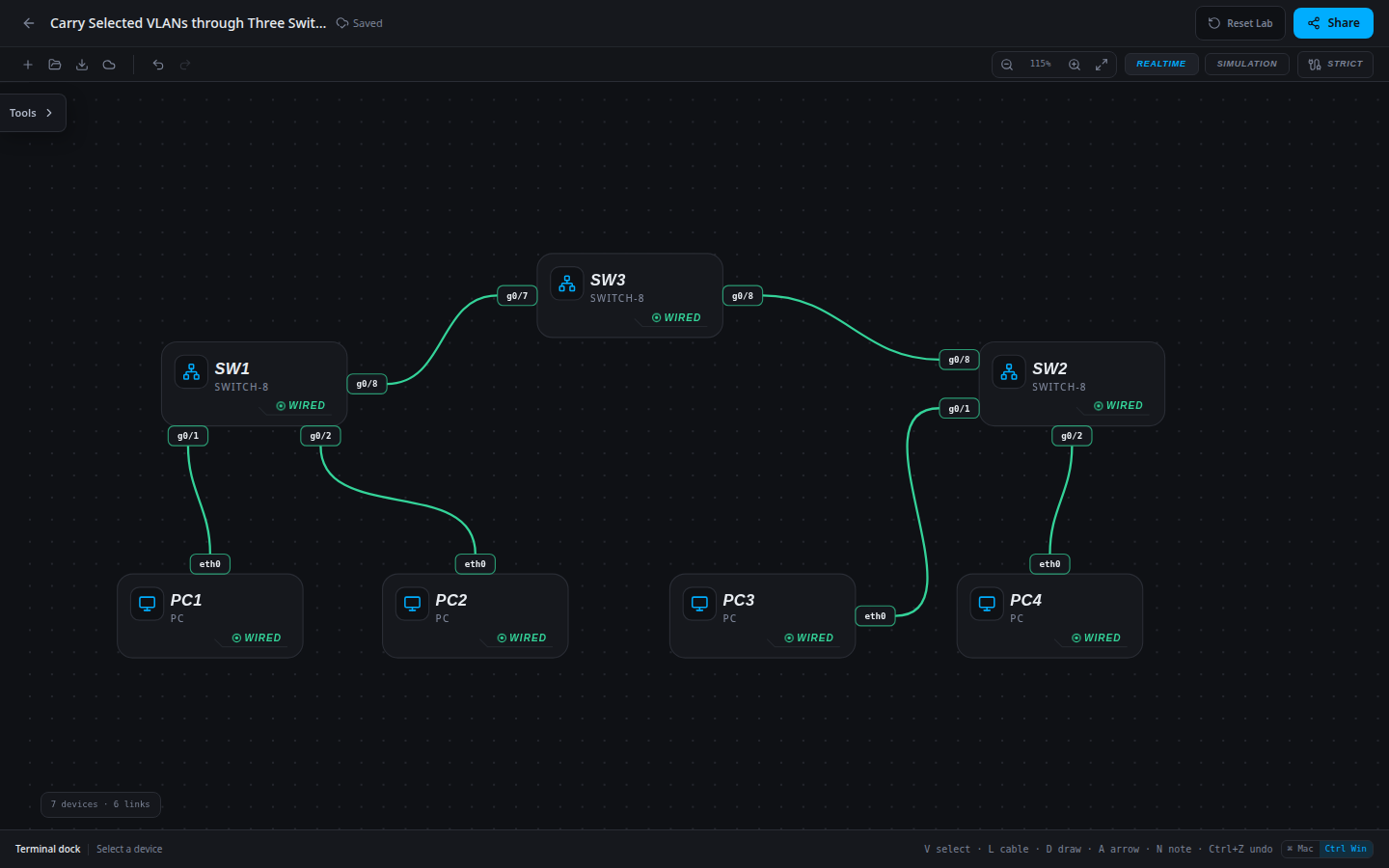
7 devices · 6 links
Scenario
A distribution switch was inserted between two access closets. The edge configurations were retained, but the new switch uplinks are still access ports. Restore both departments through the new path.
Objectives
- Translate the approved VLAN plan into switch configuration.
- Verify port membership and every trunk in the path.
- Preserve working traffic while proving the new department or uplink.
CCNA blueprint
200-301 v1.1 objectives — this lab covers the following specific skills, not every subtopic in the domain.
- 2.1.a — Configure data access VLANs.
- 2.2.a — Configure trunk ports and restricted VLAN carriage.
- 2.2.b — Use 802.1Q VLAN separation across switches.
Starting information
- The cable path is SW1 g0/8 → SW3 g0/7 → SW3 g0/8 → SW2 g0/8.
- All three switches already define VLANs 10 and 20. SW1 and SW2 have the correct host ports and trunk policy.
- Configure SW3 g0/7 and g0/8 as trunks carrying exactly VLANs 10,20. Preserve the native VLAN and host addresses.
| Host | IPv4 address | Mask | Gateway |
|---|---|---|---|
| PC1 | 192.168.10.10 | 255.255.255.0 | None |
| PC2 | 192.168.20.20 | 255.255.255.0 | None |
| PC3 | 192.168.10.30 | 255.255.255.0 | None |
| PC4 | 192.168.20.40 | 255.255.255.0 | None |
| Device / port | Device / port |
|---|---|
| PC1 / eth0 | SW1 / g0/1 |
| PC2 / eth0 | SW1 / g0/2 |
| PC3 / eth0 | SW2 / g0/1 |
| PC4 / eth0 | SW2 / g0/2 |
| SW1 / g0/8 | SW3 / g0/7 |
| SW3 / g0/8 | SW2 / g0/8 |
Tasks
- Trace the full physical path and compare trunk tables on all three switches.
- Apply the approved restricted trunk policy to both distribution-switch uplinks.
- Verify both trunk ports and the VLAN database on SW3; do not assume one working trunk proves the whole path.
- Test Students and Staff in both directions. Save the working configuration and explain where a missing allowed VLAN would interrupt each path.
Useful commands
show vlan brief
show interfaces trunk
show running-config interface g0/7
show running-config interface g0/8
copy running-config startup-config
Progressive hints
Hint 1
Separate VLAN existence, access-port assignment and trunk carriage when diagnosing the path.
Hint 2
Every switch carrying a VLAN needs that VLAN locally, and both ends of every transit link need compatible trunk policy.
Hint 3
Use show running-config interface for the affected port; compare switchport access vlan on host ports and switchport trunk allowed vlan on uplinks against the approved plan.
Verification
- The cable path is SW1 g0/8 → SW3 g0/7 → SW3 g0/8 → SW2 g0/8.
- All three switches already define VLANs 10 and 20. SW1 and SW2 have the correct host ports and trunk policy.
- Configure SW3 g0/7 and g0/8 as trunks carrying exactly VLANs 10,20. Preserve the native VLAN and host addresses.
- Student and Staff paths succeed in both directions; configuration output matches the required membership and trunk policy.
Solution / walkthrough
Show Solution
Use enable only from a > prompt; if already at #, begin with configure terminal.
SW3
The intermediate switch must carry each VLAN across both uplinks; the two edge switches already have the approved trunk policy.
enable
configure terminal
interface g0/7
switchport mode trunk
switchport trunk allowed vlan 10,20
exit
interface g0/8
switchport mode trunk
switchport trunk allowed vlan 10,20
end
copy running-config startup-config
Run every verification check above after the changes. A saved configuration alone does not prove packet delivery.