Open the lab
[ YOUR LAB FILE ]
Download the starting topology, then work through the lesson in SwitchLab.
- Save the .swlab file without renaming its extension.
- Open SwitchLab. Import and export controls currently require a desktop-width window. On a smaller screen, Tools → Fit brings the topology into view.
- Select Import Sandbox (folder icon), choose the downloaded file, and confirm the device and cable counts below.
- Select a device, then choose Open device on desktop or its name in the bottom bar on smaller screens. Select CLI for switches/routers or Desktop → Terminal for PCs. Enter
enableonly when the prompt ends in >. - Follow this page beside the simulator. Use a free account to export your work. Reimport the original download to restart; export any work you want to keep first.
Prerequisites
- Complete the focused lessons for the features used in this scenario.
- For campus policy scenarios, complete VLANs, trunks, IPv4, OSPF and ACL lessons first.
Topology
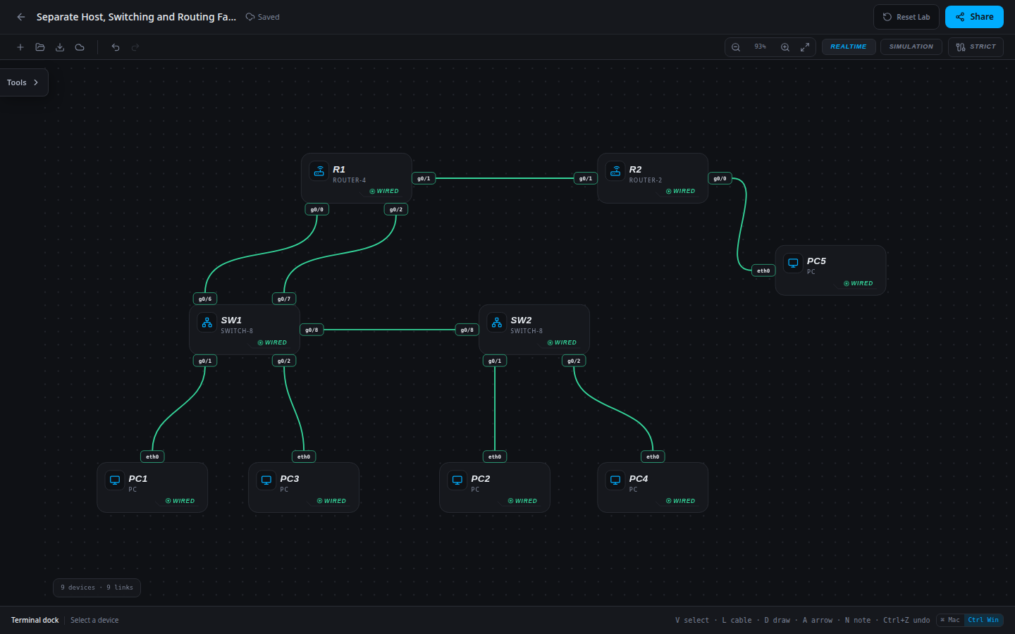
9 devices · 9 links
Scenario
PC1 reaches its local department but not the remote resource. PC4 cannot reach its Staff peer, while PC3 still reaches the resource. Use these different symptoms to avoid replacing good router configuration.
Objectives
- Implement or restore the approved network design without breaking required control paths.
- Verify configuration, end-to-end behavior and completed-network persistence.
- Produce an operational handoff with evidence and a deterministic reset path.
CCNA blueprint
200-301 v1.1 objectives — this lab covers the following specific skills, not every subtopic in the domain.
- 1.6 — Apply and verify the scenario’s IPv4 addressing.
- 2.1.a — Verify data access-port membership.
- 2.2 — Verify the restricted interswitch trunk.
Starting information
- USERS VLAN 10: PC1/PC2, subnet 10.10.10.0/24, gateway R1 g0/0=10.10.10.1. STAFF VLAN 20: PC3/PC4, subnet 10.20.20.0/24, gateway R1 g0/2=10.20.20.1.
- SW1/SW2 g0/1 are Users ports and g0/2 are Staff ports. Their g0/8 trunk carries exactly VLANs 10,20. SW1 g0/6 connects to the Users gateway; SW1 g0/7 connects to the Staff gateway.
- R1 g0/1=172.16.12.1/30 connects to R2 g0/1=172.16.12.2/30. R2 g0/0=10.30.30.1/24 serves PC5=10.30.30.50.
- Use single-area OSPF process 1: router IDs R1=1.1.1.1 and R2=2.2.2.2, area 0 on transit and LAN prefixes, LAN interfaces passive. No static routes are required.
| Host | IPv4 address | Mask | Gateway |
|---|---|---|---|
| PC1 | 10.10.10.10 | 255.255.255.0 | 10.10.10.254 |
| PC2 | 10.10.10.20 | 255.255.255.0 | 10.10.10.1 |
| PC3 | 10.20.20.30 | 255.255.255.0 | 10.20.20.1 |
| PC4 | 10.20.20.40 | 255.255.255.0 | 10.20.20.1 |
| PC5 | 10.30.30.50 | 255.255.255.0 | 10.30.30.1 |
| Router | Interface | IPv4 address | Mask |
|---|---|---|---|
| R1 | g0/0 | 10.10.10.1 | 255.255.255.0 |
| R1 | g0/2 | 10.20.20.1 | 255.255.255.0 |
| R1 | g0/1 | 172.16.12.1 | 255.255.255.252 |
| R2 | g0/0 | 10.30.30.1 | 255.255.255.0 |
| R2 | g0/1 | 172.16.12.2 | 255.255.255.252 |
| Device / port | Device / port |
|---|---|
| PC1 / eth0 | SW1 / g0/1 |
| PC2 / eth0 | SW2 / g0/1 |
| PC3 / eth0 | SW1 / g0/2 |
| PC4 / eth0 | SW2 / g0/2 |
| SW1 / g0/8 | SW2 / g0/8 |
| SW1 / g0/6 | R1 / g0/0 |
| SW1 / g0/7 | R1 / g0/2 |
| R1 / g0/1 | R2 / g0/1 |
| R2 / g0/0 | PC5 / eth0 |
Tasks
- Build a baseline matrix for local Users, local Staff and remote-resource paths from multiple sources.
- Compare the failing paths against working controls; inspect the relevant host and access-port settings before touching OSPF.
- Correct the two configuration discrepancies against the approved plan with the smallest changes.
- Prove the full matrix, export/reload and write a handoff explaining why the routed core did not need repair.
Useful commands
show vlan brief
show interfaces trunk
show running-config
show ip ospf neighbor
show ip route
copy running-config startup-config
Progressive hints
Hint 1
Break the end-to-end path into host settings, local VLAN carriage, gateway reachability, route selection and any access policy.
Hint 2
Use a working control at each layer. Do not remove security controls or add broad routes just to make one ping succeed.
Hint 3
Compare each affected host, interface and route against the approved plan; use the earlier focused lessons for the exact command patterns.
Verification
- The final network matches every approved addressing, VLAN, routing and policy requirement above.
- Every required positive path succeeds and every forbidden path remains blocked.
- Completed export/reload retains the result; reimporting the starter restores the original exercise.
Solution / walkthrough
Show Solution
Use enable only from a > prompt; if already at #, begin with configure terminal.
PC1
Correct the host gateway after local delivery and working Staff routing isolate the fault.
netsh ip set 10.10.10.10 255.255.255.0 10.10.10.1SW2
Restore the remote Staff port while retaining the working trunk and routing.
enable
configure terminal
interface g0/2
switchport access vlan 20
end
copy running-config startup-config
Run every verification check above after the changes. A saved configuration alone does not prove packet delivery.